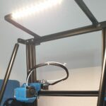
See a sharp camera image even in the dark: If only there was light! With 3D printer lighting, you can get a good camera image even in poor lighting conditions.
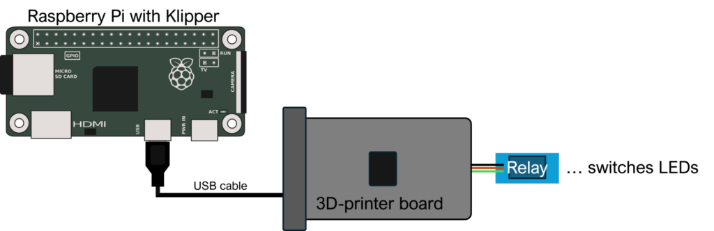
There are various approaches to installing light for a 3D printer with Klipper. An external light source can be switched via a smart switch with Tasmota, for example. Also the GPIO pins of the Raspberry Pi can be used to switch LEDs. In this tutorial, I use the pins of the 3D printer mainboard to control an LED strip. For this purpose, the free pins of the mainboard are controlled with gCode commands from the Klipper web interface and can be switched on and off.
content
Materials
!!! The following links are the stores where I bought the materials or serve as an example of the products used. I do not receive any commission or other consideration!
- Relay board 5V
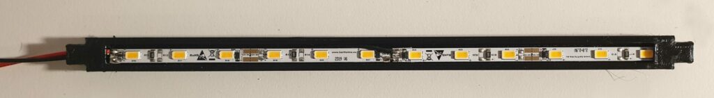
- LED-stripes 12V
- Jumper-cable female/female
- Bracket for the LED strip on the printer see Thingiverse or Printables
- optimum: Circuit diagram of your own 3D printer mainboard
Structure
Electronics
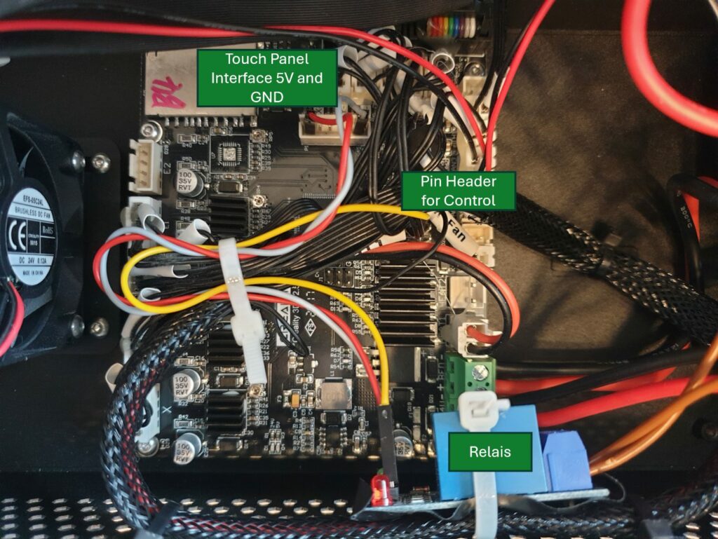
First step is to install the electronics. I could not find a good documentation for my board, a Creality 3D V2.5.2 that explains the pinout on the board. However, there is a pin header with labeling on the mainboard. The pins D12, D11, A11 and A12 are conveniently led out of the board. I used A11 for the relay (yellow cable).
For the relay module you also require a 5V power supply. I got GND and 5V, via the unused touch panel socket and attached the insulated relay board to the side wall of the housing. If everything is connected and fixed, the function of the 3D-printer light is tested for the first time.
Function test of the relay
To test the function of the relay with Klipper, go to the web interface. There we open the printer.cfg file under Machine, then printer.cfg and create this macro:
# Case Light
[output_pin caselight]
pin: PK4 #A12 the Pin used for the Relay
pwm: false
shutdown_value: 0

# LED-Control
[gcode_macro lights_off]
gcode:
    SET_PIN PIN=caselight VALUE=0

[gcode_macro lights_on]
gcode:
    SET_PIN PIN=caselight VALUE=1

[gcode_macro lights_toggle]
gcode:
    {% if printer["output_pin caselight"].value == 0 %}
        lights_off
    {% else %}
        lights_on
    {% endif %}
The macro is used to set pin A12 to HIGH or LOW. The wiring will vary for a different mainboard. So you have to choose a different pin on the board. However, Klipper cannot do anything with the pinnumber A12 and will throw an error when saving the printer.cfg. To switch pin A12, you need the pin designation of pin A12 from Amtel, the manufacturer of the microcontroller on my mainboard. In my case, pin A12 is PK4 on the mainboard with an ATMega2560, as visible on the pinout documentation of the microcontroller
Once the correct pin has been found and there are no more error messages from Klipper after saving the printer.cfg, the Pi has to be restarted. When rebooted Mainsail shows three new buttons at the dashboard under Macros. If the Macros field is not visible, it can be activated in the settings under Dashboard. Now you can control the lighting relay using the buttons in the Klipper web interface. If you trigger the macro with the buttons and you can hear the click of the relay everything is correct. Otherwise you may have to take a look if your pin in the macro is correct. Now it’s time to set up the LED-light for the 3D-printer.
LED-Installation
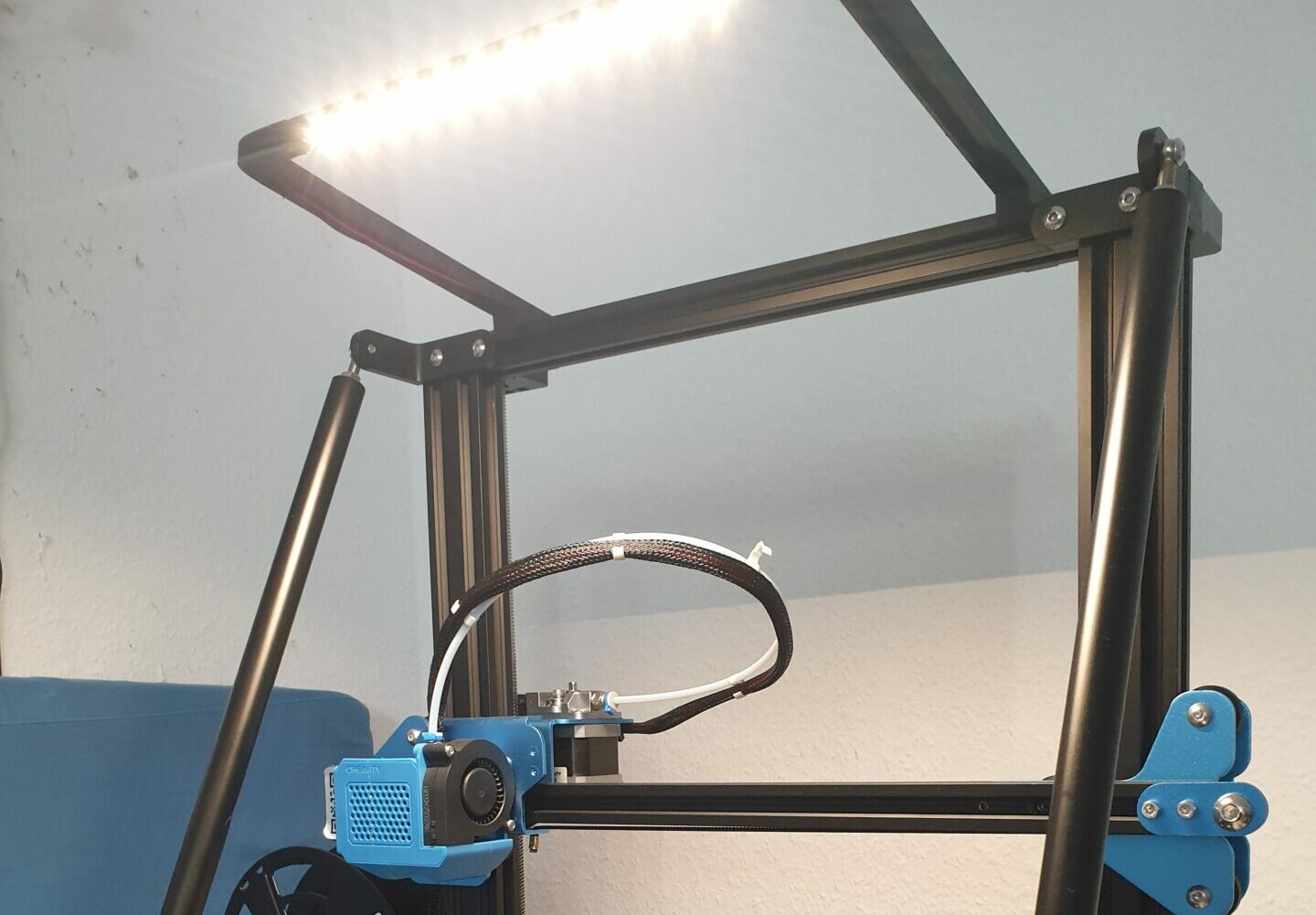
An external power supply unit or the power supply unit of the 3D printer can be used to power the LED strip. In my case, I use the 24V 3D printer power supply. I connected two short LED strips in parallel to the power supply unit to reduced the voltage to 12V per strip.
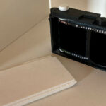
LED holder
When printing my LED holder, I only used support for the LED tray and printed the side parts without support. If the side parts are to be printed with support, care must be taken not to block the cable guides in the front part with support material. If everything is printed it can be put together an installed. To costumise the holder for your own printer I uploaded the .step files. They can also be found on printables and thingiverse alongside the .stl files, so that the width of the LED tray can be easily adjusted.
This method can be used to equip almost any 3D printer with Klipper and also with Marlin to bring LED light to life, operated via the printer’s web interface and works like factory-installed lighting. Make a 360 degree photo of you 3D-printing room? Take a look at how to built or make 360 degree photos.
Some more interesting articles
- Integrating Solax X3 Hybrid G4 API into Home Assistant

- Photo album the different way – How to turn a camera in a personal picture collection
- 3D-printer light with klipper
Thanks a lot!